design considerations for flex circuit pcb
Designing flexible circuit PCBs (flex PCBs) involves a unique set of considerations that distinguish them from traditional rigid PCBs. These considerations are crucial to ensure the flex PCB performs optimally, maintains reliability, and meets the specific requirements of its intended application. Here are the key design considerations for flex circuit PCBs:
The choice of materials is foundational in flex PCB design. The substrate material, typically polyimide, is chosen for its flexibility, durability, and thermal stability. Copper is the preferred conductor material due to its excellent electrical conductivity and flexibility. The type of adhesive used also plays a significant role, as it must maintain strong bonds without degrading under mechanical stress or thermal cycling. The materials selected must withstand the environmental conditions to which the flex PCB will be exposed.
One of the primary advantages of flex circuit pcb is their ability to bend and flex. Designers must carefully consider the bend radius, which is the minimum radius the flex circuit can be bent without causing damage. A larger bend radius is generally more desirable to minimize stress on the circuit. It’s also important to design the PCB to avoid bending near component solder joints, as these areas are more prone to stress and potential failure.
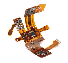
What are the design considerations for flex circuit pcb?
Flex PCBs can be single-sided, double-sided, or multi-layered. The number of layers impacts the flexibility, thickness, and overall performance of the PCB. Multi-layer flex PCBs offer more routing options and can support more complex designs but are less flexible and more expensive. Designers must balance the need for additional layers with the impact on flexibility and cost.
The layout and routing of traces in a flex PCB require meticulous planning. Traces should be designed to accommodate the mechanical stresses that occur during bending and flexing. It’s advisable to use curved traces rather than sharp angles, as sharp angles can concentrate stress and lead to trace cracking. Additionally, traces should be evenly spaced and avoid crossing each other at angles to prevent electromagnetic interference and signal integrity issues.
Flex PCBs often need mechanical support to ensure durability and reliability. Stiffeners, made from materials like FR4 or stainless steel, are added to provide rigidity in specific areas, such as around connectors or components. These stiffeners help prevent excessive flexing and mechanical fatigue, which can lead to circuit failure. Designing the PCB with appropriate reinforcement in high-stress areas is crucial.
Component placement on a flex PCB must account for both mechanical and electrical considerations. Placing components in areas that experience the least amount of flexing can prolong the lifespan of the solder joints. Surface-mount technology (SMT) is commonly used, but through-hole components can also be used if properly supported. It’s essential to ensure that components are securely attached and that the layout minimizes mechanical stress on the solder joints.
Flex PCBs, like all electronic circuits, generate heat. Effective thermal management is necessary to prevent overheating and ensure reliable performance. Designers must consider the thermal properties of the materials and include features such as thermal vias, heat sinks, or conductive pathways to dissipate heat efficiently. Proper thermal design helps maintain the integrity and longevity of the flex PCB.
The environmental conditions where the flex PCB will operate must be considered. This includes exposure to moisture, chemicals, temperature extremes, and mechanical vibrations. Protective coatings, such as conformal coatings or encapsulation, can be applied to shield the flex PCB from environmental hazards. Ensuring the design accommodates the specific environmental challenges is essential for reliability and performance.
Finally, rigorous testing and validation are crucial in the design process. Flex PCBs should undergo various tests, including thermal cycling, bending fatigue, and environmental exposure tests, to ensure they meet the required standards and specifications. These tests help identify potential issues and verify that the design is robust and reliable for its intended application.
In summary, designing flex circuit PCBs involves careful consideration of materials, flexibility, layer stack-up, trace layout, mechanical support, component placement, thermal management, environmental factors, and thorough testing. Addressing these considerations effectively ensures the creation of a reliable and high-performing flex PCB tailored to its specific application requirements.